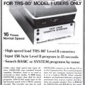
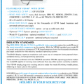
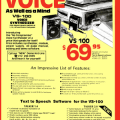
The Radio Shack "expansion box"
The TRS-80 Model I was designed to allow for external expansion through what Steve Leininger described as an “expansion port” (the TRS-80 card edge connector). Many people assumed that Radio Shack was developing a S-100 based expansion box to attach to the Model I. (The S-100 was a popular bus standard at the time.)
The first issue of the Radio Shack Microcomputer Newsletter in late 1977 contained a section answering some common questions about the new TRS-80 computer. One answer gave some details about the upcoming “expansion box”:
What are the specifications on the expansion box?
It will be a 5-slot motherboard, with a 7-8 amp power supply. We have decided not to go S-100 because we can build our own more efficient bus at a lower cost and pass the savings on to you, the consumer – a Radio Shack tradition. Some of the cards we plan to offer include:
- Extra memory 8K & 16K
- Color graphics
- D/A converters
- RS-232 interface
- serial and parallel ports
- MODEM
- second cassette interface
This sounded pretty impressive and in line with the Apple II, which had eight slots for expansion. But the specifications had changed considerably by the time the second issue of the Radio Shack Microcomputer Newsletter in early 1978 announced the “Expansion Interface":
TRS-80 EXPANSION INTERFACE
This is the key to the expandability of the TRS-80. The Expansion Interface (which usually requires Level II BASIC) enables you to add the following to the TRS-80:
- Additional RAM (16K or 32K)
- Dual cassettes (program selectable)
- Mini-floppy disks. It will handle up to four minis!
- Our new line printer (Centronics parallel port).
The EXPANSION INTERFACE includes a real time clock, a space for an additional PC board (to add whatever?), and continuation of the TRS-80 bus. The EXPANSION INTERFACE will give you the capability to fully utilize your TRS-80 system.
These specifications were far more limited than those given for the “expansion box”. Instead of five slots, the only expansion was the “space for an additional PC board”. This was later described as the “Expansion Board Compartment” in the Expansion Interface manual.
The phrase “to add whatever?” wasn’t very specific, and as far as I know, only an optional RS-232 board made use of the compartment. But the manual did provide technical details and dimensions for the PC board and stated:
If you have enough experience in digital electronics, you might even design your own circuit and install it in this compartment.
Without any slots, all hardware add-ons for the Model I either installed internally (usually with soldering) or attached directly to the card edge connector (which caused problems if more than one add-on was needed). A slot system of the type promised for the “expansion box” would have made adding hardware a lot easier.


